This page describes a number of different options for connecting one or more pushbuttons to a PC and use them to control the photobooth mode shooting mode.
Note: For a simple setup you can use the PC's mouse to control the photobooth by selecting the "Use mouse left button to start and right button to toggle between B&W and color" option in the photobooth settings.
StealthSwitch
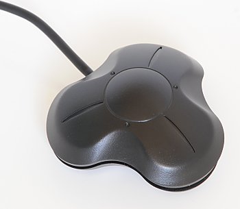
The StealthSwitch is a robust foot switch which plugs straight into a USB port and makes an ideal switch for photobooth operation. It is very simple to use: just plug it in to any spare USB port, wait a few seconds for Windows to recognize it and you're ready to go. In full screen photobooth mode pressing the StealthSwitch button will start the photobooth sequence - that's all there is to it.
Note: If you have already installed the "desktop cloaking" software that comes with the StealthSwitch you need to disable it otherwise every time you press the button the photobooth display will be hidden.
Arcade Style Buttons
There are several ways arcade style buttons can be connected to a PC and used to control the photobooth including the StealthSwitch 3 and the serial port method. The StealthSwitch 3 is simpler to setup than the serial port method but is a little more expensive. Both the StealthSwitch 3 and the serial port methods are described in detail below.
StealthSwitch 3
The StealthSwitch 3 is similar to the original StealthSwitch described above but has two important differences:
1) You can connect external buttons which simply plug into standard 3.5mm sockets (the same as used by most MP3 players)
2) Each button is programmable allowing it to send any key press or sequence of key presses you like
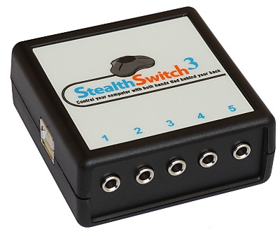
StealthSwitch 3 showing the five 3.5mm sockets for connecting external buttons on the front and the USB port on the side
Please note: The StealthSwitch 3 is functionally identical to the StealthSwitch II which it replaces.
Instructions to add an arcade style button using the StealthSwitch 3:
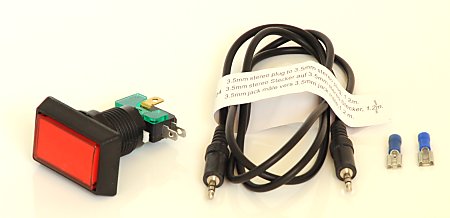
These are the components required to add an arcade style button: the button, stereo cable with 3.5mm jacks and two female spade connectors
1) Cut off the jack plug from one end of the stereo cable and bare the wires
2) Plug the USB cable from the StealthSwitch II and plug the remaining 3.5mm jack from the stereo cable into one of the StealthSwitch sockets
3) Run StealthSwitch Configuration Utility and select "Keyboard test mode". When you press the each button you should see something like this:
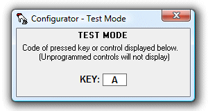
4) Release the switch and identify the correct wires to use from the stereo cable by shorting two of them together. When the correct pair of wires are shorted together the keyboard test window will show A, B, C, D or E
5) Attach the spade connectors to each of the two wires identified in step 4. Use a crimp tool or solder them to ensure they are firmly attached
6) Connect the wire to the arcade switch using the spade connectors and press the button to check that the keyboard test window shows A, B, C, D or E
You should now have an arcade button attached to a cable with a 3.5mm jack plug which looks something like this:
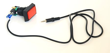
Finally use the StealthSwitch Configuration Utility to program each of the buttons to send the required key strokes. The best way to do this is to right click on the required button in the main Configurator window and select "Macro 1", click on "1st KEY" and type the first key in the macro e.g. function key F4 to start the photobooth sequence. If the macro has more than one key, e.g. Ctrl+B to select black and white mode, click on "1st KEY" and press (and release) the Ctrl key then click on "2nd KEY" and press C. When you've finished press the Program button to program the StealthSwitch 3 (you only need to do this once - the StealthSwitch 3 will remember the settings and can be used on any computer). The StealthSwitch 3 is now ready to be used to control the photobooth.
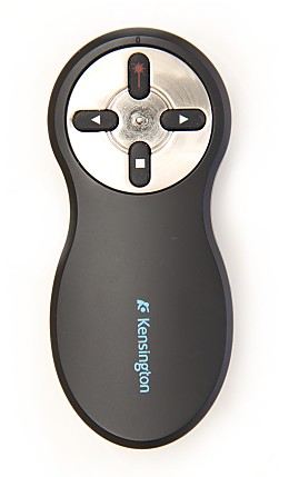
This provides a simple and effective way for the operator to wirelessly control the photobooth. The following keyboard shortcuts can be accessed using the Kensington Wireless Presenter:
laser pointer button (F5) - start the photobooth sequence
left arrow (Page Up) - decrease the number of copies to print
right arrow (Page Down) - increase the number of copies to print
stop button (b) - reprint last set of photos
Serial Port Method
What you need
| 1. | Unless the PC has a serial port you will need a USB to RS-232 adaptor such as the StarTech.com USB to RS-232 Serial DB9 Adaptor. This is not the cheapest adaptor available, but it does work on Windows XP and Windows Vista. |
| 2. | DB9 socket and wires or an old RS-232 cable with a DB9 socket |
| 3. | A suitable "push to make" button. The arcade style button below was purchased from Gremlin Solutions in the UK. This site in the US has a good selection of buttons: www.happcontrols.com |
| 4. | Photobooth Pushbutton Utility, PhotoboothBtn_Webcam.exe, which can be found in the Webcam Photobooth installation folder |

Connecting it up
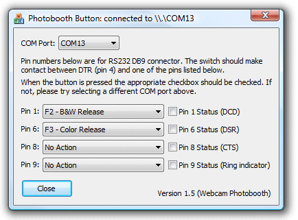
First install the driver software that comes with the USB to serial to RS-232 adaptor and connect it to a USB port on your PC. Then run the Photobooth Pushbutton utility (PhotoboothBtn_Webcam.exe):
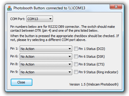
Next identify the correct COM port for the serial port. This can be done by using a small piece of wire and connecting pins 1 and 4 on the DB9 connector (shown below). If the correct COM port is selected the "Pin 1" checkbox in the Photobooth Pushbutton utility should be checked when pins 1 and 4 are connected. If nothing happens try selecting a different COM port from the drop down list.
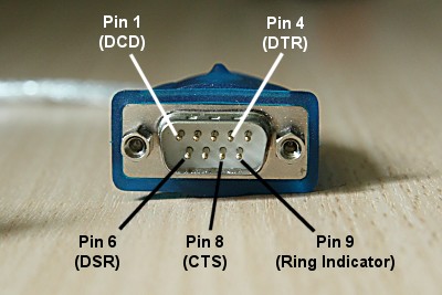
Now wire up the button or buttons to the appropriate pins on the DB9 socket e.g. if you're using two buttons pin 4 should be connected to the "common" connections of the two buttons and pin 1 should be connected to the "push to make" connection of one button and pin 6 to the "push to make" connection of the other button. Normally the connections would be made by soldering the wires to the DB9 connector but if you're not happy with soldering you can use an RS-232 cable instead and simply cut off one end, identify which wires to use and then connect them to the spade connections on the buttons using crimp connectors.
Once the buttons are connected they can be tested by observing whether the appropriate checkboxes are checked in the pushbutton utility app when each button is pressed.
Finally, select the required action for each button using the drop down lists in the pushbutton utility e.g. for a two button setup with Webcam Photobooth where the user can select B&W or color prints you would use settings similar to those below:
In operation
Connect the USB to RS-232 adaptor to a USB port on the PC and, making sure no buttons are pressed, run the Photobooth Pushbutton utility. Before running Webcam Photobooth check that the buttons are working properly by pressing them and making sure the correct checkbox in the pushbutton utility is checked. It may be necessary to select a different COM port if the buttons don't work. Normally the same COM port is assigned provided the USB to RS-232 adaptor is connected to the same USB port each time.
Next run Webcam Photobooth, select fullscreen photobooth mode and you should be able to use the buttons to trigger the photobooth sequence. The Photobooth Button utility needs to running at all times during photobooth operation so that it can detect the button presses and forward them to Webcam Photobooth.